Garrattfan's Modelrailroading Pages
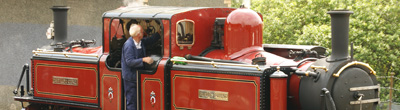
Fairlie Merddin Emrys
7.4 Detailing: top side
Intermezzo |
|
The area of the manifold is a beast on both sides. Again the manual is not very clear about it, probably because it is next to impossible to describe the intricate tangle in decent English. The photos can only show so much from any given angle and you need to look at many photos independently to construct a 3D image of what pipe is going where and for what reason. And then there is the complication of simplification (now, is that a nice oxymoron?). I mean this: there are many, many pipes and every pipe has joints, bends and valves. You can model only so much in a given time frame and with any given level of detail. Inevitably you have to simplify things to ever finish the model. At least I had to make compromises otherwise I would be building this loco forever. After work on the model ceased after the spring of 2017 I had already started work on the top side manifold. In the following autumn when resuming the work waslon overdue it dawned on me that I had been procrastinating over and over again, dreading all the details I needed to address without a clear picture in my head. In June I had been in Wales to meet Merddin and Friends (David Lloyd George, Earl of Merioneth and Taliesin) and to take lots of detail photos to clarify things only to find that the piping arrangement had thoroughly changed after Merddin's latest overhaul in 2015. So the photos, however nice to see and document the loco in real life, were not going to be overly useful. In late November 2017 I collected all my courage and took the jump. I decided to leave out many small pipes and get on with it. Anyone criticising me for it, be my guest, buy the kit yourself and build a better model. |
|
To workI resumed work on the locomotive with the bottom end manifold [273-275] |
|
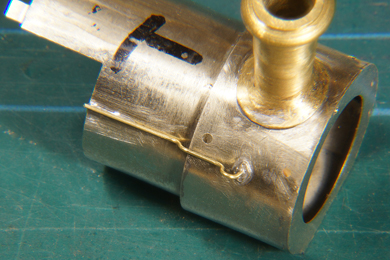
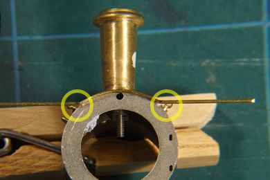
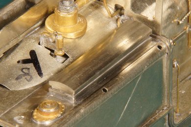
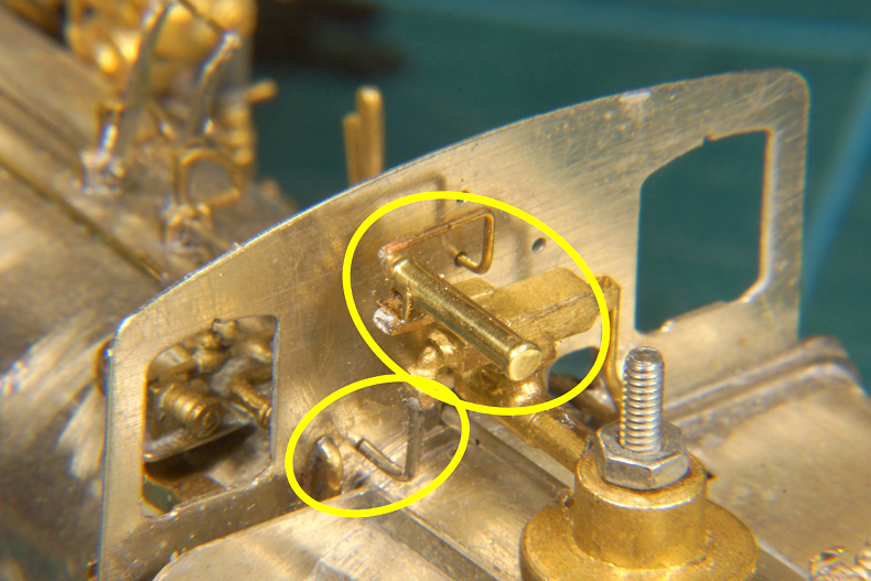
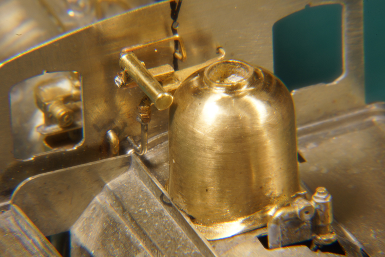
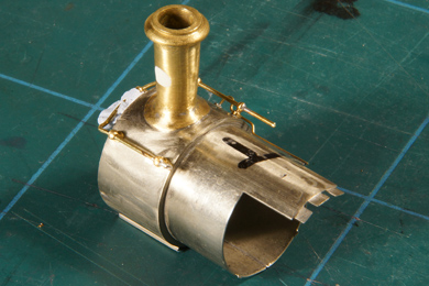
The first act of the restart of the project in the winter of 2017. I added the chime whistle on the top side of the locomotive [275]. The manual recommends to add it after painting but I will mask the whistle during painting. I prefer the more robust fastening by soldering over any glue. I polished the whistle before soldering. I also added a pipe running into the from the side of the manifold. |
|
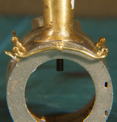
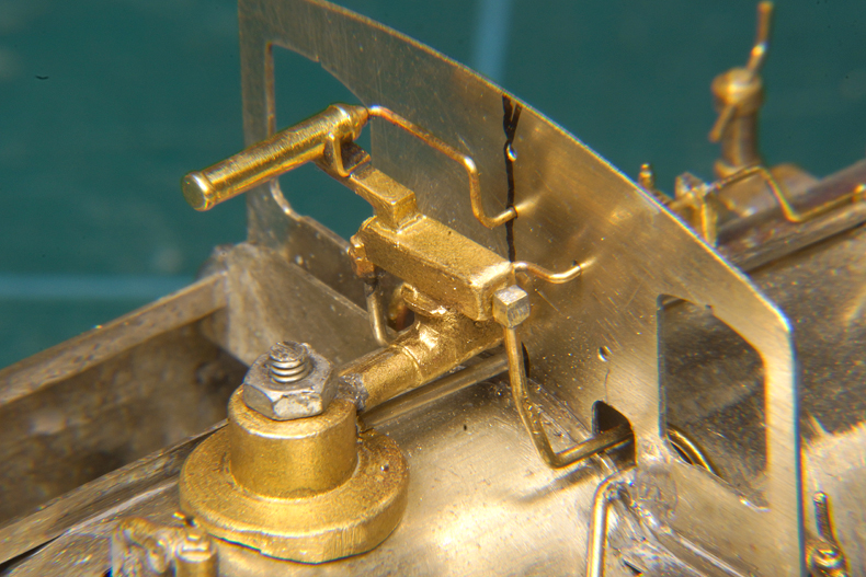
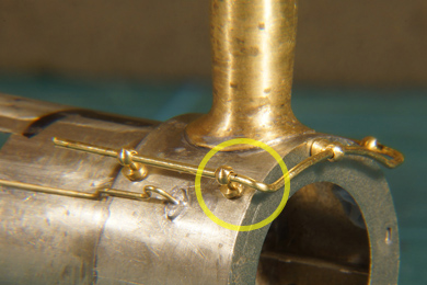
The pipe running down from the manifold was soldered (right on the photo). This made the dome base permanent, until now I could still remove it to work on it. I also shortened the bolt of the dome base to avoid any interference inside the dome. I also added a pipe in the back of the manifold which in hindsight should have been straight, but what's done is done. |
|
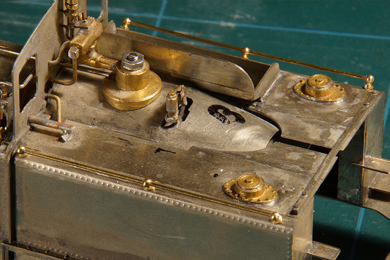
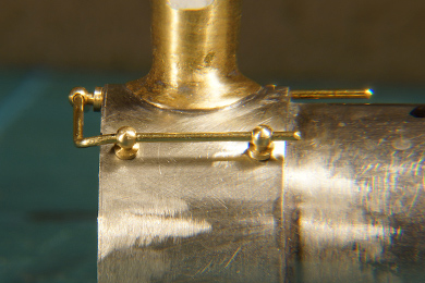
Top cab side at the back of the manifold. |
|
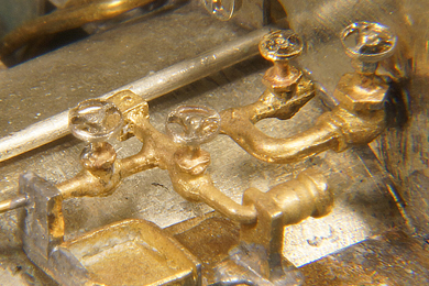
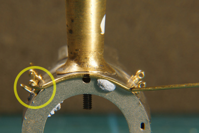
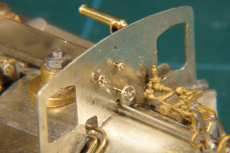
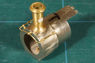
The three stubs were shortened and hand wheels fitted [271-272] |
|
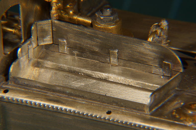
The dome is trial fitted. It needed some filing before it would sit well. I used the black line in the centre of the cab front to aim the dome sitting straight. It is a pity but there is little else you can do but scrape a bit off the dome. A greedy board needs to be added to the coal bunker (it serves to increase coal capacity) so I need to do that first before I finalise the dome's shape. |
|
The greedy board in place. I soldered only the four tabs in order to keep the prototypical seam to show up. |
|
 |
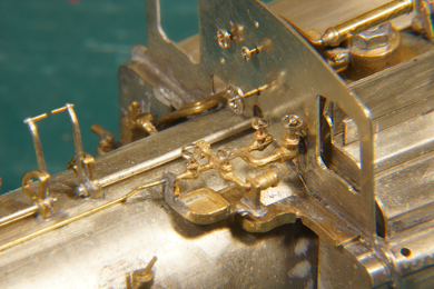
Handwheels are prepared and added to the complex casting of valves on fireman's side of the cab [271-272] |
 |
 |
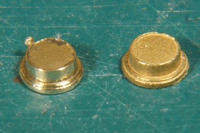 |
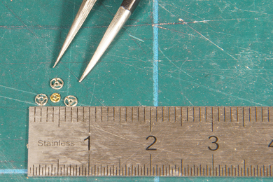
The vacuum gauges are prepared [268-269]. They are both sanded (400 and 800) smooth and then polished. The left one is already done en the right one is the original as supplied for the sake of the photo before being treated as well. |
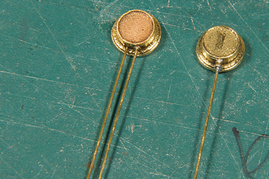 |
Holes of 0.3 mm are drilled and 0.3 mm wires of sufficient length are inserted and soldered. Note that the two gauges are different. The one with one pipes is the top end gauge (the other one goes at the bottom end).
As the gauges will be left brass coloured I will have a hard time masking them when they are in the cab during the painting process. So I will store them for now and glue them in place AFTER painting. |
 |
|
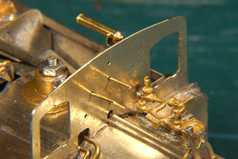
A small pipe is added on the fireman's side of the top end smoke box. This pipe is not described in the manual but it is clearly visible on the photos of the fireman's side. I guess it is also an exhaust pipe of some sort. First drill a 0.5 mm hole half way between the two handrail mounting holes, about 2 mm below the line through those holes. The minute mounting plate is included in the etches but it is extremely delicate. Cut it out of the etch with the greatest care you can muster. Do not attempt to file or sand it but solder it directly over the 0.5 mm hole with 188C solder. It is fiddly but it can be done. Only after soldering it file and sand the mounting plate to your taste and remove superfluous solder. Bend the pipe according to the photos. First solder the back end (closest to the midst of the locomotive) with a tad of 188C solder. See to it that the 180 degree turn of the pipe sits perpendicular to the surface of the smokebox. Then solder the front end of the pipe from the inside of the smokebox with a blob of 140C detail solder. Get in and out quickly with a hot iron and it will be fixed before the 188C solder holding the mounting plate in place will melt. Good for your adrenaline! |
|
 |
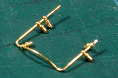
The handrails on all four tanks are made [208-210] |
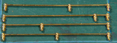 |
As they are to remain blank, I have not soldered them. I stored them for now and once the loco has been painted I will them in place. |
Next is the handrail on the smokebox front [211-220]. The manual already states that making the handrail is less easy. One logical way is to start at one end and gradually work your way through the bends and twists to the other end. I chose however to start in the middle and work my way outward in a symmetrical fashion. One complication I had is that I want the handrails to remain removable, like the straight handrails on the tanks, because they are to remain blank. This means that the four knobs on the sides cannot be soldered to the smokebox and you cannot use them as I firm, fixed base. I used Blu-Tack to keep them in place. |
|
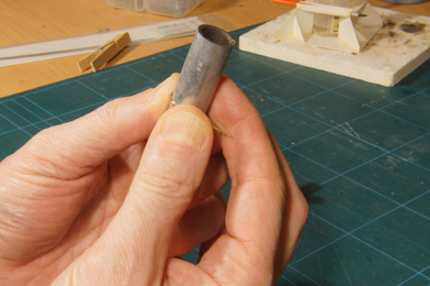 |
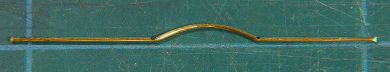
I took an end of 0.7 mm wire with a length of approximately 6 cm and put a mark in the middle. I bent the wire over a pipe of 15mm diameter to obtain the right curve, working away from the middle mark until I got to the point where the first bend was to be located. The manual recommends using a round piece of 20 mm diameter but the wire is springy and that made for too large a radius. The radius of the curve is kept about the same as the outer diameter of the smokebox. |
 |
Once happy the places of the knobs on either side are marked and a corresponding bend is made. See to it that the result lies dead on a flat surface. On the photo both ends form a straight line, but later I made the bends a bit sharper pointing the ends a little upwards. Check and check again. If you do not get it right at this stage it is light work to start all over again but incredibly hard to correct if you ignore it. |
 |
The first bend 90 degrees backwards is made and carefully checked against the mark in the middle. If happy FIRST INSERT THE MIDDLE KNOB (I tend to forget such things when I am so hard at work) and then make the other bend. This one is very critical. You have only a few tenths of a millimetre play or else the knobs will be popped out of their place. If you get it wrong it is possible to bend the 0.7 mm wire back but only once to make a second attempt. If you need a third attempt the wire will inevitably break. |
Finally the front of the wire is tilted a bit down in front of the leading knobs. I find it unaesthetic but it is prototypical.
Check the correct alignment of the wire from all sides ==> |
 |
 |
<= Here the "duck down" in the front of the hand rail is clearly visible. You have to guesstimate the height of the curve of the wire and the position of the middle knob while bending so it eventually ends perfectly in the middle hole. |
Solder the rail to the end knobs, and the END KNOBS ONLY. You need to leave the leading knobs loose if you want to be able to remove and replace the handrail. |
You can now remove the handrail by prying the end knobs carefully apart. The protruding ends are cut short and filed and sanded to the form of the knob. |
|
Replacing the handrail is done as follows
|
 |
The toolbox is placed [279] |
|
|
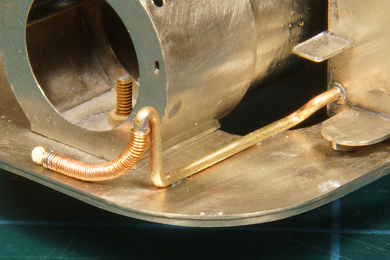
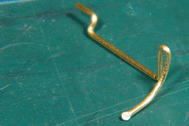
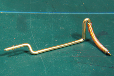
The brake pipe and hose are primarily bent from the conveniently soft 1.2 mm copper wire that is supplied with the kit [288-289]. Care must be taken that the rear end slots into the hole in the water tank. This hole must be enlarged a bit. The vertical part of the pipe must protrude a little ahead of the smokebox front and rises to halfway the smokebox then turns nearly 180 degrees ands falls back to the apron in a gentle curve. Study photos well. The coupler is made by flattening the end of the copper wire in a pair of pliers, followed by a bit of filing to shape. This coupler should lie right in front of the middle of the smokebox on the apron.
The outer end of the brake pipe is a hose. To mimick the hose I wrapped a thin strand of transformer wire around the copper base and soldered the outer ends. Note that I slid a ring on the rear end of the pipe, which will be soldered to the tank. |
 |
Then the pipe was soldered on the apron and to the tank. |

Sign my
GuestBook